We continue with reconstructing a phase space for Detour Gold Corp. (DGC-T). Disclosure -- long position (which long predates my use of this analytical tool).
A two-dimensional phase space can be reconstructed from a time series by creating a scatter plot of the time series against a lagged copy of itself. By doing so we create a plot which is topologically equivalent (though not absolutely identical to) a phase space consisting of the time series plotted against its first time derivative.
How much of a lag should we choose. It should be intuitively obvious that the lag should not be too small. If, for instance, we had pricing data for our stock that was collected at one-second intervals, a lag of 1 s would probably not show very interesting dynamics, as 1 s is not enough time for much to happen with price (except very rarely).
The price data in the DGC pricing time series is at one-day intervals, so that one day should be the smallest lag we can look at. Well, we could look at a zero lag plot, but it is not very interesting.
 The zero-lag 2-d phase space for Detour Gold. Actually, it does show something interesting--there is something of a gap in price from about $25 to $27 and $28 to $29. But we could have learned that from a simple one-dimensional plot.
A lag of one day (for instance plotting Friday's closing price against Thursday's, etc.) looks a little more interesting. . .

It is a little difficult to make out where the graph starts, but its ending stands out, with the last price in our time series being just above $31. Here is the phase space with a lag of two days . . .

Many of the same features are present, but the curve diverges a little more from the diagonal line. Even though equivalent features can be found in both of the lagged time series, the specific shape of corresponding features changes somewhat from one lag to another.
Here is the phase space with a lag of three days.

And for four . . .

Nothing much new here. The overall form is the same, however you may notice that the lower part of the plot is spread away from the diagonal more than is the case in the one-day-lag phase space. The last plot also is not quite as tangled as the one-day-lag phase space.
Overall, this is not a very interesting plot. Part of it is because the dynamics of the stock performance over the last nine months has not been very interesting--at least from a dynamics perspective (it is always interesting to see a stock for which one has a long position rising).
The reason for the minor differences in the reconstructed phase spaces has to do with the connection between the lag, and the portion of the curve over which the slope (the first derivative) is calculated. When we used the price difference last time, we were actually using that as an estimate of the slope of the tangent to the price function. When I chose to take the price difference over a two-day period (and then divided by two), I was estimating the tangent slope from two points that were separated by two days.
 In the small diagram at left, we are interested in finding the slope of the tangent (yellow line) to the curve at point T.
By using the price difference over two days, we calculate the slope of the green line segment, which is our estimate of the slope of the yellow line.
Because the only data we actually have are represented by the red blobs, we cannon find the slope of the yellow line directly.
The lag plot essentially estimates the slope of the yellow line differently.
 For the one-day lag, your estimate of the slope is the short red line segment; for the two-day lag, the orange segment; three-day lag, the green; and for the four day lag, the estimate for the slope of the yellow tangent line is the slope of the blue segment.
Clearly, none of these look like particularly good estimates. So what is the relative merit of choosing one lag over another.
If the time series is especially busy, with a lot of variability, then the slopes estimated between neighbouring points will similarly show a lot of variability. If the the slopes are estimated between points that are farther apart (longer lag), there will be less variability.
The choice of a lag can therefore be influenced by the scale of the dynamics of interest. If you are interested in short timescale dynamics, you need to use a short lag, and if you are interested in longer-term dynamics, you need to use a longer lag.
The formal rules (first minimum of the average mutual information) is selected because this maximizes the differences between the two axes so that the maximum information is revealed.
Unfortunately, the DGC plots don't show a lot of interpretable dynamics. So let's look at some functions with some interesting dynamics.
 The plot at left shows the plot of the proxy function for global ice volume over the past million years. Data from Shackleton et al. (1990).
In various papers and presentations over the past ten years I have used this record and others to study global climate dynamics.
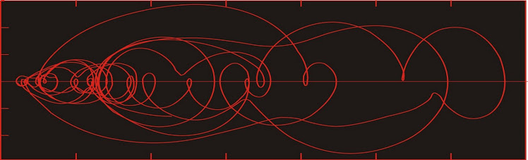
The2-d state space reconstructed below used a lag of 6,000 years and covers about half of the record shown above (from 500,000 years ago until present).
 Now here we have a phase space which allows us to interpret a lot about the dynamics of the system. It is a little complex, and like other plots above, it just consists of numerous clockwise loops overlapping each other.
The record would look better rendered in three dimensions, as the apparent intersections would be shown to be areas where the function passes beneath itself.
In the coming discussions we will look at ways to clarify the plot at left and see what can be interpreted from it.
Reference:
Shackleton N J, Berger A, Peltier W R. An alternative astronomical calibration of the lower Pleistocene timescale based on ODP Site 677. Trans R Soc. Edinburgh Earth Sci, 1990, 81: 251―261.
A two-dimensional phase space can be reconstructed from a time series by creating a scatter plot of the time series against a lagged copy of itself. By doing so we create a plot which is topologically equivalent (though not absolutely identical to) a phase space consisting of the time series plotted against its first time derivative.
How much of a lag should we choose. It should be intuitively obvious that the lag should not be too small. If, for instance, we had pricing data for our stock that was collected at one-second intervals, a lag of 1 s would probably not show very interesting dynamics, as 1 s is not enough time for much to happen with price (except very rarely).
The price data in the DGC pricing time series is at one-day intervals, so that one day should be the smallest lag we can look at. Well, we could look at a zero lag plot, but it is not very interesting.

A lag of one day (for instance plotting Friday's closing price against Thursday's, etc.) looks a little more interesting. . .

It is a little difficult to make out where the graph starts, but its ending stands out, with the last price in our time series being just above $31. Here is the phase space with a lag of two days . . .

Many of the same features are present, but the curve diverges a little more from the diagonal line. Even though equivalent features can be found in both of the lagged time series, the specific shape of corresponding features changes somewhat from one lag to another.
Here is the phase space with a lag of three days.

And for four . . .

Nothing much new here. The overall form is the same, however you may notice that the lower part of the plot is spread away from the diagonal more than is the case in the one-day-lag phase space. The last plot also is not quite as tangled as the one-day-lag phase space.
Overall, this is not a very interesting plot. Part of it is because the dynamics of the stock performance over the last nine months has not been very interesting--at least from a dynamics perspective (it is always interesting to see a stock for which one has a long position rising).
The reason for the minor differences in the reconstructed phase spaces has to do with the connection between the lag, and the portion of the curve over which the slope (the first derivative) is calculated. When we used the price difference last time, we were actually using that as an estimate of the slope of the tangent to the price function. When I chose to take the price difference over a two-day period (and then divided by two), I was estimating the tangent slope from two points that were separated by two days.

By using the price difference over two days, we calculate the slope of the green line segment, which is our estimate of the slope of the yellow line.
Because the only data we actually have are represented by the red blobs, we cannon find the slope of the yellow line directly.
The lag plot essentially estimates the slope of the yellow line differently.

Clearly, none of these look like particularly good estimates. So what is the relative merit of choosing one lag over another.
If the time series is especially busy, with a lot of variability, then the slopes estimated between neighbouring points will similarly show a lot of variability. If the the slopes are estimated between points that are farther apart (longer lag), there will be less variability.
The choice of a lag can therefore be influenced by the scale of the dynamics of interest. If you are interested in short timescale dynamics, you need to use a short lag, and if you are interested in longer-term dynamics, you need to use a longer lag.
The formal rules (first minimum of the average mutual information) is selected because this maximizes the differences between the two axes so that the maximum information is revealed.
Unfortunately, the DGC plots don't show a lot of interpretable dynamics. So let's look at some functions with some interesting dynamics.

In various papers and presentations over the past ten years I have used this record and others to study global climate dynamics.
The2-d state space reconstructed below used a lag of 6,000 years and covers about half of the record shown above (from 500,000 years ago until present).

The record would look better rendered in three dimensions, as the apparent intersections would be shown to be areas where the function passes beneath itself.
In the coming discussions we will look at ways to clarify the plot at left and see what can be interpreted from it.
Reference:
Shackleton N J, Berger A, Peltier W R. An alternative astronomical calibration of the lower Pleistocene timescale based on ODP Site 677. Trans R Soc. Edinburgh Earth Sci, 1990, 81: 251―261.
No comments:
Post a Comment